Introduction
Choosing an angular contact ball bearing for high-speed service is less about matching dimensions and more about controlling heat, stiffness, preload, and fatigue under demanding operating conditions. Small specification errors can raise friction, promote skidding, or shorten bearing life long before the system reaches its intended speed. This article outlines the key factors that drive selection, including contact angle, preload strategy, load direction, lubrication, and speed limits, so you can evaluate bearing options with a clearer understanding of how each decision affects reliability, thermal behavior, and overall machine performance.
Why Angular Contact Ball Bearing Selection Affects Reliability
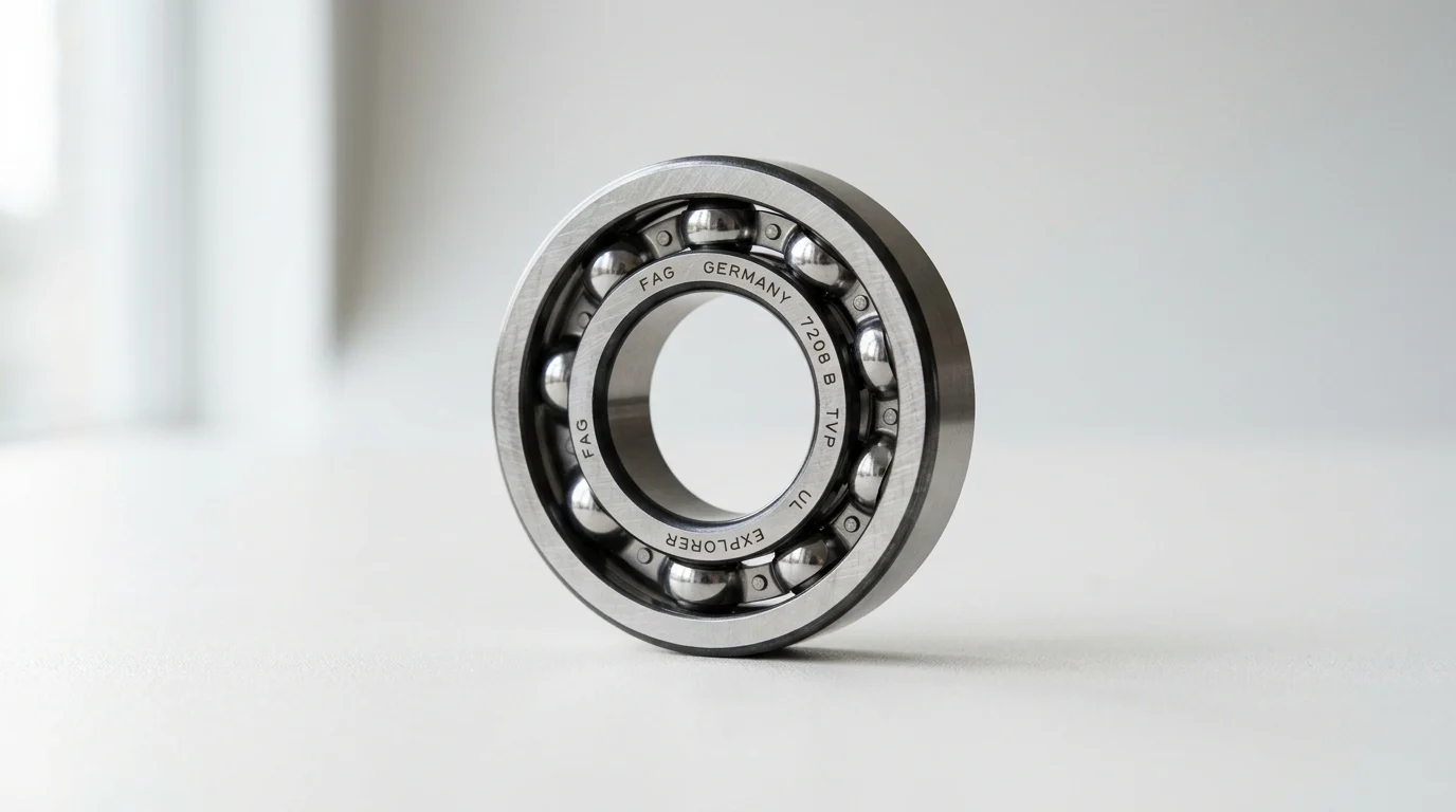
In high-speed rotating equipment, the angular contact ball bearing serves as the critical interface between dynamic power transmission and static housing. Selecting the correct bearing architecture directly dictates the operational reliability and thermal stability of systems such as machine tool spindles, turbomachinery, and aerospace actuators. When rotational speeds exceed 1.5 million dN (bore diameter in millimeters multiplied by speed in RPM), the margin for error in bearing specification narrows significantly, making rigorous selection protocols mandatory.
Speed, preload, and failure risk
The relationship between rotational speed, internal preload, and catastrophic failure is highly non-linear. As angular contact ball bearings accelerate, centrifugal forces drive the rolling elements outward against the outer ring raceway. This dynamic action alters the operational contact angle and can increase the effective internal preload by up to 30% at speeds exceeding 15,000 RPM.
If the initial static preload is specified too high, this dynamic increase triggers thermal runaway, leading to rapid lubricant degradation and premature micro-spalling. Conversely, inadequate preload allows the balls to skid rather than roll, generating severe adhesive wear and cage failure. Mastering this balance is the primary driver of long-term mechanical reliability.
Operating conditions to define first
Before evaluating specific bearing geometries, engineers must establish a precise envelope of operating conditions. This requires mapping the maximum and continuous radial and axial loads, quantifying the anticipated operating temperature range, and defining the duty cycle.
For example, a spindle operating continuously at 24,000 RPM requires a vastly different thermal management strategy than a mechanism executing rapid, intermittent accelerations to 30,000 RPM. Establishing these baseline parameters ensures that subsequent decisions regarding contact angles and materials are grounded in empirical operational data rather than generic performance estimations.
Key Technical Selection Criteria

Translating operational parameters into physical bearing specifications requires a deep understanding of internal geometry and mechanical constraints. The angular contact ball bearing is uniquely designed to accommodate combined loads, but optimizing it for high-speed environments demands precise configuration of its internal architecture.
Contact angle, geometry, cage, and preload
The contact angle is the fundamental geometric variable dictating load distribution and speed capability. Standard high-speed configurations typically utilize 15° or 25° contact angles. A 15° angle minimizes the spin-to-roll ratio, reducing internal friction and allowing for maximum rotational speeds, though it sacrifices axial rigidity. A 25° angle provides a balanced compromise, increasing axial stiffness while reducing the maximum speed threshold by approximately 15% to 20% compared to a 15° variant.
Additionally, cage design is critical; high-speed applications frequently utilize lightweight, outer-ring-guided cages machined from phenolic resin or PEEK. These advanced polymers minimize centrifugal mass, reduce friction against the rolling elements, and prevent catastrophic cage resonance at extreme velocities.
Speed limits and performance factors
Speed limits are strictly governed by the dN factor and the complex interplay of internal friction, preload class, and lubrication. To navigate these variables, engineers rely on comparative performance factors to match bearing geometry with the kinematic demands of the application.
| Contact Angle | Relative Maximum Speed | Relative Axial Load Capacity | Typical Application Focus |
|---|---|---|---|
| 15 Degrees | 100% (Baseline) | Low | Ultra-high-speed milling spindles |
| 25 Degrees | 80% – 85% | Medium | Universal high-speed machining |
| 40 Degrees | 50% – 60% | High | Heavy thrust loads, ballscrews |
Selecting the optimal angle requires calculating the exact ratio of axial to radial loads; specifying a high contact angle for an application dominated by radial loads will induce poor ball tracking and accelerate fatigue.
Comparing Bearing Options
Beyond internal geometry, the selection of materials and lubrication methodologies represents the most significant opportunity to push the performance boundaries of an angular contact ball bearing. The evolution of advanced ceramics and precision lubrication systems has fundamentally altered high-speed bearing capabilities.
Steel vs hybrid ceramic bearings
The industry standard for precision bearings is high-carbon chromium steel (such as 52100 or 100Cr6), which provides excellent fatigue life under moderate conditions. However, high-speed applications increasingly demand hybrid ceramic bearings, which pair steel rings with silicon nitride (Si3N4) rolling elements.
Silicon nitride balls are approximately 60% lighter than their steel counterparts. This drastic reduction in mass minimizes centrifugal forces and gyroscopic slip at the outer raceway, allowing hybrid bearings to achieve speeds 20% to 30% higher than all-steel variants. Furthermore, the dissimilar materials eliminate the risk of cold welding (galling) under marginal lubrication conditions and significantly reduce thermal expansion within the bearing core.
Lubrication methods and tradeoffs
Lubrication is not merely a maintenance consideration; it is a primary design constraint. Standard grease lubrication is highly cost-effective and simplifies housing design, but it is generally limited to operating speeds of approximately 1.0 to 1.2 million dN due to thermal accumulation and grease channeling limitations.
To achieve speeds exceeding 2.0 million dN, engineers must specify oil-air (or minimal quantity lubrication) systems. Oil-air systems inject precise, metered micro-droplets of oil directly into the bearing contact zone at intervals of 1 to 5 minutes. This provides an optimal elastohydrodynamic film thickness while simultaneously utilizing the compressed air to cool the bearing and create positive pressure to prevent contaminant ingress.
Specification, Sourcing, and Compliance Checks
Specifying the optimal angular contact ball bearing is only the first phase of the engineering process. Ensuring that the procured components meet exact specifications, originate from qualified suppliers, and are handled correctly is essential to preserving the engineered reliability of the high-speed system.
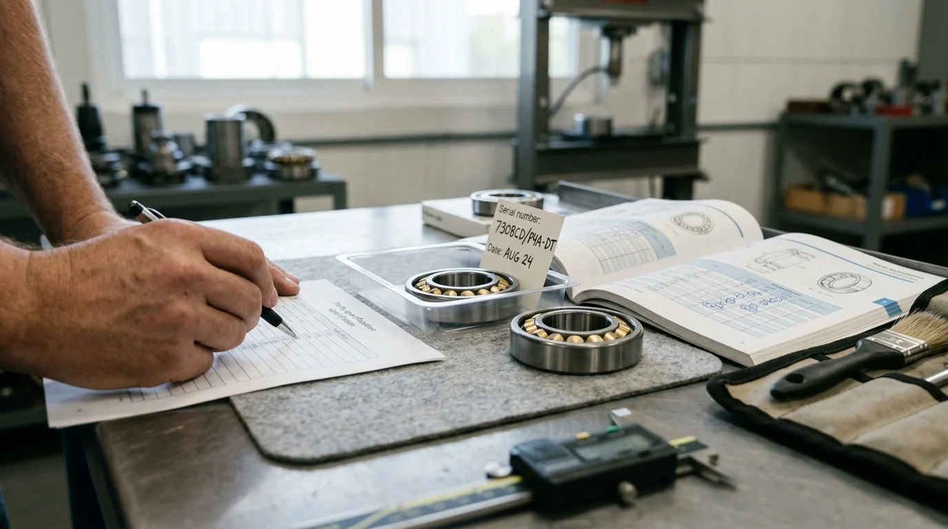
Critical specification and mounting data
Precision tolerances are non-negotiable in high-speed applications. Bearings must be specified to stringent ABEC (Annular Bearing Engineering Committee) or ISO standards. For spindle-grade applications, ABEC 7 (ISO P4) or ABEC 9 (ISO P2) tolerances are mandatory. These classes dictate extremely tight controls on bore diameter, outer diameter, and radial runout.
| Precision Class | Max Radial Runout (50mm Bore) | Dimensional Tolerance (Bore) | Application Suitability |
|---|---|---|---|
| ABEC 5 (ISO P5) | 5.0 µm | 0 to -8 µm | Standard electric motors |
| ABEC 7 (ISO P4) | 2.5 µm | 0 to -6 µm | High-speed spindles, aerospace |
| ABEC 9 (ISO P2) | 1.5 µm | 0 to -4 µm | Ultra-precision grinding heads |
Mating components must adhere to corresponding geometric dimensioning and tolerancing (GD&T) standards. Mounting an ABEC 9 bearing on a shaft with 5.0 micrometers of runout completely negates the bearing’s precision and induces destructive harmonic vibrations.
Supplier qualification and comparison points
Supplier qualification requires rigorous auditing of manufacturing capabilities and quality management systems. Buyers should mandate ISO 9001 certification as a baseline, with AS9100 required for aerospace applications.
Key comparison points during supplier evaluation include demonstrated defect rates (target benchmarks often fall below 50 Parts Per Million) and traceability protocols. Furthermore, lead times for ultra-precision angular contact ball bearings can stretch from 12 to 16 weeks due to the complex grinding and matching processes, requiring procurement teams to establish robust forecasting and safety stock agreements to prevent assembly line disruptions.
Handling, storage, installation, and logistics
The high-speed capabilities of an ABEC 7 or 9 bearing can be instantly destroyed by improper handling. Installation must occur in a cleanroom environment, ideally meeting ISO Class 7 standards, to prevent particulate contamination.
Bearings must remain in their original, sealed packaging until the exact moment of installation to prevent oxidation and degradation of the factory-applied rust preventative. Additionally, storage facilities must maintain strict climate controls, typically holding ambient temperatures between 20°C and 25°C with relative humidity strictly below 60%.
Finalizing the Selection Decision
The final selection of an angular contact ball bearing requires synthesizing geometric parameters, material science, and supply chain realities into a cohesive engineering decision. This phase demands strict adherence to a structured evaluation process to avoid costly over-specification or catastrophic under-performance.
Step-by-step selection process
A systematic selection process begins with calculating the required dN value and mapping the maximum dynamic loads. Second, engineers must select the contact angle that provides the necessary axial stiffness without exceeding thermal limits at the target speed.
Third, the choice between all-steel and hybrid ceramic construction is evaluated based on the dN threshold and required fatigue life. Fourth, the lubrication methodology is finalized, balancing the simplicity of grease against the high-speed capability of oil-air systems. Finally, the precision class and exact preload values are defined, ensuring the bearing will interface correctly with the machined tolerances of the shaft and housing.
Decision rules for performance tradeoffs
Decision rules often require navigating strict performance and economic tradeoffs. For instance, specifying hybrid ceramic bearings introduces a cost multiplier of 2.0x to 3.0x compared to standard steel bearings. However, if the application operates in a marginal lubrication environment, the hybrid ceramic bearing may deliver three to five times the operational lifespan, resulting in a significantly lower total cost of ownership.
Similarly, engineers must balance preload against speed; increasing the preload class from ‘Light’ to ‘Medium’ increases system rigidity by roughly 20%, but simultaneously reduces the maximum permissible speed by 10% to 15% due to increased frictional heat generation. Finalizing the selection means quantifying these exact tradeoffs against the primary operational objectives of the machine.
Key Takeaways
- The most important conclusions and rationale for angular contact ball bearing
- Specs, compliance, and risk checks worth validating before you commit
- Practical next steps and caveats readers can apply immediately
Frequently Asked Questions
How do I choose the best contact angle for high-speed use?
Use 15° for maximum speed and lighter axial loads, 25° for a speed-stiffness balance, and 40° mainly for heavier thrust loads. Match the angle to your real axial/radial load ratio.
When should I select a hybrid ceramic angular contact ball bearing?
Choose hybrid ceramic when speed is very high, heat must be reduced, or longer spindle life is needed. Silicon nitride balls lower centrifugal force and help control skidding at elevated RPM.
Why is preload so important in high-speed angular contact ball bearings?
Too much preload can raise friction, temperature, and thermal runaway risk; too little can cause ball skidding and cage damage. Set preload based on speed, load, lubrication, and duty cycle.
What application data should I prepare before requesting a bearing from DEMY Bearings?
Provide bore size, RPM, radial and axial loads, operating temperature, lubrication method, duty cycle, and mounting arrangement. This helps DEMY recommend a suitable precision angular contact bearing more accurately.
Can DEMY Bearings support OEM or distributor sourcing for angular contact ball bearings?
Yes. DEMY supplies catalog-based bearing options for OEMs, distributors, and equipment manufacturers, with precision-focused production and testing support for industrial high-speed applications.