Introduction
Selecting an angular contact ball bearing requires more than matching bore size and outside diameter. Because these bearings carry combined radial and axial loads through a defined contact angle, the right choice depends on how the load is applied, the operating speed, required stiffness, lubrication conditions, and expected service life. This introduction outlines the key factors that influence bearing performance, including single versus paired arrangements, preload, material and cage options, and application demands. With these basics in view, the rest of the article will help you evaluate specifications more accurately and avoid choices that lead to heat, premature wear, or reduced machine reliability.
Why choosing the right angular contact ball bearing matters
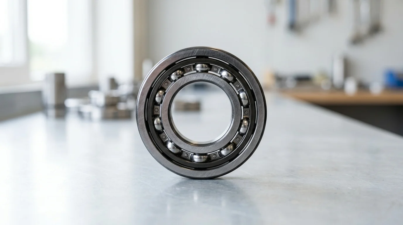
Specifying the correct angular contact ball bearing is a fundamental engineering requirement for rotary systems subjected to combined radial and axial loads. Unlike standard deep groove variants, angular contact architectures feature asymmetric raceways that transmit forces across a predetermined contact angle. This geometric advantage allows them to support significant unidirectional thrust loads alongside radial forces, making them indispensable in machine tool spindles, industrial pumps, and high-performance gearboxes.
For engineering and procurement teams, bearing selection goes far beyond matching dimensional envelopes. The rigorous demands of modern industrial applications necessitate a deep understanding of internal kinematics, load distribution, and thermal dynamics. Failing to align the bearing specifications with the operational environment compromises system integrity, inflates maintenance budgets, and drastically reduces the mean time between failures (MTBF).
Load direction, speed, stiffness, and service life
The primary operational parameters dictating angular contact ball bearing selection are load direction, rotational speed, and required system stiffness. Because these bearings support axial loads in only one direction, they are typically installed in pairs or multiplex sets. The dynamic load rating (C) and static load rating (C0) serve as the foundation for calculating the L10 basic rating life. In mission-critical applications such as continuously operating centrifugal pumps, engineers typically target an L10 service life exceeding 100,000 hours.
Speed capabilities are heavily influenced by the internal contact angle and the bearing’s rolling elements. Applications demanding rapid acceleration and high rotational velocities, such as CNC machine tool spindles, often require speed factors (n × dm) exceeding 1.0 × 10^6 mm/min. To achieve this, engineers must carefully balance the contact angle against the required stiffness. A lower contact angle increases speed capacity by minimizing centrifugal ball loads, whereas a higher contact angle maximizes axial stiffness and load-carrying capacity.
Operating risks of incorrect bearing selection
Incorrect bearing selection introduces severe operational risks that propagate throughout the mechanical system. Mismatched preload levels or inadequate contact angles frequently lead to excessive Hertzian contact stress, resulting in subsurface micro-cracking and eventual spalling of the raceways. Furthermore, insufficient axial load under high-speed conditions can cause the balls to skid rather than roll, stripping the elastohydrodynamic lubrication film and inducing rapid adhesive wear.
Thermal instability is another critical consequence of poor selection. If a bearing with excessive preload is subjected to high-speed operation, internal friction torque generates significant heat. When operating temperatures spike above 120°C, standard bearing steel (52100) experiences dimensional instability, and standard lubricants rapidly degrade. This thermal expansion further tightens internal clearances, creating a runaway thermal feedback loop that culminates in catastrophic bearing seizure.
Key angular contact ball bearing specifications to evaluate
Evaluating angular contact ball bearings requires a systematic analysis of their internal geometry, component materials, and environmental protections. Each parameter interacts with the others to define the bearing’s kinematic behavior, thermal limits, and overall suitability for the intended application.
Contact angle, row design, and arrangement
The contact angle is the most defining characteristic of an angular contact ball bearing. Standard industrial offerings typically feature contact angles of 15°, 25°, or 40°. A 15° angle is optimized for high-speed applications with predominant radial loads, whereas a 40° angle is designed to handle heavy axial loads at moderate speeds.
| Contact Angle | Primary Strength | Typical Application | Relative Speed Limit |
|---|---|---|---|
| 15° (e.g., C suffix) | High rotational speed | Machine tool spindles | Highest |
| 25° (e.g., E/A5 suffix) | Balanced radial/axial load | Precision motors | Medium |
| 40° (e.g., B suffix) | High axial load capacity | Pumps, compressors | Lowest |
Beyond the angle, row design and arrangement dictate system rigidity. Single row bearings must be adjusted against a second bearing. When deployed in pairs, they can be arranged Back-to-Back (DB) for high moment-load rigidity, Face-to-Face (DF) for compliance with minor misalignments, or Tandem (DT) to share heavy unidirectional axial loads.
Preload, internal clearance, cage material, and raceway design
Preload is an intentionally applied internal force that eliminates clearance and increases system rigidity. Preload classes are generally categorized into Light (Class A), Medium (Class B), and Heavy (Class C). For instance, a heavy preload of 1,500 N might be applied to a spindle bearing to eliminate chatter during aggressive metal cutting, though this sacrifices maximum speed capability.
Cage material selection directly impacts thermal and speed limits. Glass-fiber reinforced polyamide 66 cages are lightweight and offer excellent sliding properties, but are typically limited to continuous operating temperatures of 120°C. For temperatures up to 150°C or environments involving aggressive chemical lubricants, machined brass or phenolic resin cages are mandated. Raceway design, particularly the degree of osculation (the ratio of raceway radius to ball diameter), determines the contact ellipse size and directly influences the bearing’s static load limit.
Speed limits, temperature, contamination, and sealing
The thermal reference speed and limiting speed of an angular contact ball bearing indicate the maximum RPM achievable before heat generation outpaces heat dissipation. Operating beyond these thresholds requires advanced lubrication strategies, such as air-oil mist systems. Temperature limits are not solely dictated by the steel, but often by the sealing materials.
When contamination is a risk, proper sealing is critical. Non-contact metallic shields (ZZ) offer low friction but minimal fluid protection. Contact seals (2RS) made from Nitrile Butadiene Rubber (NBR) provide excellent dust and moisture exclusion but are generally restricted to an operating temperature range of -40°C to +100°C. For high-temperature environments, Fluoroelastomer (FKM) seals are required, extending the thermal limit up to +200°C at the cost of higher initial torque.
How angular contact ball bearings compare with other bearing types
While angular contact ball bearings are highly specialized, they are frequently evaluated against standard deep groove ball bearings (DGBB) and tapered roller bearings (TRB). Selecting the optimal rolling element technology requires a clear understanding of the mechanical trade-offs inherent to each design.
When angular contact ball bearings are the better choice
Angular contact ball bearings are the superior choice when an application demands a precise balance of high rotational speed and rigid axial support. Deep groove ball bearings can handle moderate axial loads, but their symmetrical raceway design limits their thrust capacity and makes them susceptible to ball truncation under heavy axial forces. Conversely, while tapered roller bearings offer massive load capacities due to their line-contact geometry, they generate significantly higher friction.
In precision applications, such as high-speed centrifuges or electric vehicle reduction gearboxes operating at 10,000 RPM, the friction torque in an angular contact ball bearing is typically 20% to 30% lower than that of an equivalently sized tapered roller bearing. This lower friction translates directly into reduced parasitic power loss, lower operating temperatures, and extended lubricant life.
Comparison criteria for specification decisions
When determining the final specification, engineers must weigh radial capacity, axial capacity, and kinematic limits. The following comparison matrix highlights the functional boundaries of these three common bearing architectures, assuming equivalent bore diameters.
| Bearing Type | Radial Load Capacity | Axial Load Capacity | Max Speed Capability | Friction Level |
|---|---|---|---|---|
| Deep Groove Ball Bearing | High | Low to Moderate (Bi-directional) | Very High | Lowest |
| Angular Contact Ball Bearing | Moderate | High (Uni-directional) | High | Low |
| Tapered Roller Bearing | Very High | Very High (Uni-directional) | Moderate | Moderate to High |
If the primary design constraint is extreme shock loading at low speeds, the tapered roller bearing is preferred. However, if the specification mandates sub-micron runout accuracy combined with high-speed continuous operation, precision-class angular contact ball bearings are the only viable solution.
A practical process for selecting and sourcing
Transitioning from theoretical engineering to practical procurement requires a stringent selection and sourcing methodology. Sourcing angular contact ball bearings, particularly precision classes, involves navigating complex supply chains, verifying metallurgical quality, and ensuring long-term availability.
Step-by-step selection workflow
The selection workflow must follow a rigorous, sequential path to prevent costly redesigns. First, engineers must define the exact load profile, calculating equivalent dynamic bearing loads (P). Second, the optimal contact angle is selected to balance the radial-to-axial load ratio. Third, the arrangement (DB, DF, or DT) and preload class are established based on the required shaft stiffness.
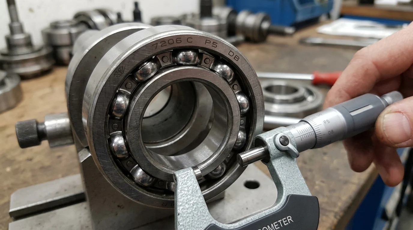
Finally, tolerance classes must be specified. For general industrial gearboxes, standard ISO P0 (ABEC 1) or P6 (ABEC 3) tolerances are sufficient. However, for precision applications like aerospace actuators or machine tools, engineers must specify ISO P4 (ABEC 7) or ISO P2 (ABEC 9) tolerances, where radial runout is restricted to less than 2.5 micrometers.
Supplier capability, quality documentation, and traceability
Supplier qualification is paramount for angular contact ball bearings due to their sensitivity to manufacturing deviations. Procurement teams must audit suppliers for advanced manufacturing capabilities, demanding comprehensive quality documentation. This includes material certificates verifying the use of high-purity, vacuum-degassed bearing steel (such as 100Cr6 or 52100) and heat treatment records confirming a raceway hardness of 58 to 62 HRC.
Traceability ensures that in the event of premature failure, the root cause can be isolated. Premium manufacturers etch unique serial numbers on precision bearing rings, tying the specific component back to its exact manufacturing batch, dimensional inspection report, and raw material heat lot.
Compliance, lead time, inventory, and aftermarket support
Global sourcing introduces additional layers of compliance and logistical complexity. Bearings and their applied lubricants must comply with regional environmental directives, including RoHS and REACH regulations. Furthermore, the supply chain for specialized high-precision bearings is often constrained.
Typical lead times for custom or high-precision ABEC-7 angular contact bearings can range from 12 to 24 weeks. To mitigate stockout risks and protect production schedules, procurement teams should negotiate blanket orders, establish vendor-managed inventory (VMI), or calculate safety stock levels based on historical MTBF data to ensure uninterrupted aftermarket support.
How to finalize the best bearing choice

Finalizing the angular contact ball bearing selection is the culmination of aligning mechanical theory with commercial reality. The final review must validate both the technical integration into the mating components and the financial impact on the overall project lifecycle.
Specification checklist for fit and preload strategy
Before releasing the final bill of materials, engineers must execute a strict specification checklist regarding shaft and housing fits. Because angular contact ball bearings rely on precise internal geometry, improper interference fits can inadvertently alter the preload. For example, a standard j5 tolerance on the shaft combined with an H6 tolerance on the housing must be mathematically verified against the bearing’s internal clearance.
Thermal expansion must also be accounted for in the preload strategy. If the operational temperature differential (Delta T) between the rotating shaft and the stationary housing exceeds 10°C, the inner ring will expand faster than the outer ring. In a rigid Back-to-Back (DB) arrangement, this thermal gradient will drastically increase internal preload, potentially pushing the bearing past its operational thermal limit.
Balancing technical margin, availability, and total cost
The ultimate decision requires balancing the technical safety margin against component availability and Total Cost of Ownership (TCO). Over-specifying a bearing—such as demanding ABEC 7 tolerances for a low-speed agricultural pump—adds unnecessary expense without yielding operational benefits. Upgrading from an ABEC 1 to an ABEC 7 bearing can increase the individual component cost by more than 300%.
Conversely, under-specifying a bearing to save upfront costs in a critical asset is a false economy. In high-volume manufacturing environments, unexpected spindle failures can result in machine downtime costs exceeding $5,000 per hour. By selecting the correct angular contact ball bearing—optimized for the exact load, speed, and thermal environment—organizations ensure maximum asset reliability and long-term operational profitability.
Key Takeaways
- The most important conclusions and rationale for angular contact ball bearing
- Specs, compliance, and risk checks worth validating before you commit
- Practical next steps and caveats readers can apply immediately
Frequently Asked Questions
What contact angle should I choose for an angular contact ball bearing?
Use 15° for high-speed spindles, 25° for balanced speed and load, and 40° for heavier axial loads in pumps or compressors. Match the angle to your speed, thrust direction, and stiffness needs.
When should angular contact ball bearings be used in pairs?
Use pairs when axial loads act in both directions or when higher rigidity is needed. Choose DB for better moment stiffness, DF for minor misalignment tolerance, and DT for heavy one-direction axial loads.
How does preload affect bearing performance?
Proper preload improves stiffness and running accuracy. Too much preload raises heat and friction; too little can cause skidding at high speed. Select preload based on speed, load, and temperature conditions.
What key application data should I prepare before ordering from DEMY Bearings?
Provide shaft and housing sizes, radial and axial loads, speed, temperature, lubrication method, arrangement preference, and expected life. This helps DEMY recommend a suitable angular contact ball bearing from its catalog.
How can I avoid early failure in angular contact ball bearings?
Choose the correct contact angle, preload, and arrangement, and ensure proper lubrication and fit. Avoid overload, poor alignment, and excessive temperature. For demanding OEM use, request precision and quality options suited to your machine.