
Introduction
Choosing ball bearings for industrial equipment involves more than matching bore size and speed ratings. The right selection depends on how the machine actually operates: radial and axial loads, rotation speed, duty cycle, temperature, contamination, lubrication method, and required service life all affect performance. A bearing that is too light-duty can fail early and disrupt production, while an oversized option can add cost, friction, and unnecessary complexity. This article explains the key criteria engineers and maintenance teams should review before selecting a bearing, so you can compare options more accurately, reduce failure risk, and align component choice with reliability, efficiency, and maintenance goals.
Why correct ball bearing selection matters for industrial equipment
Industrial machinery relies heavily on precise rotational movement, making ball bearings critical components in the mechanical drivetrain. Selecting the correct bearing is not merely a matter of matching shaft dimensions; it requires a rigorous engineering analysis of the application’s kinematic and environmental demands. When specified correctly, these components operate seamlessly for years, but miscalculations during the selection phase inevitably compound into systemic mechanical failures.
Impact on uptime, efficiency, and maintenance
The direct correlation between bearing selection and equipment uptime is well documented in reliability engineering. Statistical analyses of rotating equipment indicate that bearing failures account for approximately 40% to 50% of all motor breakdowns. When a bearing is under-specified for its load or improperly sealed, the resulting premature failure can halt production lines, incurring downtime costs that frequently exceed $10,000 per hour in continuous process industries.
Conversely, over-specifying a bearing increases rotating mass and parasitic drag, which degrades system efficiency and inflates initial capital expenditures without delivering proportional lifecycle benefits. Achieving this balance ensures the machine hits its targeted Mean Time Between Failures (MTBF) while optimizing energy consumption.
Operating conditions to define before selection
Before evaluating bearing catalogs, engineers must quantify the operational baseline. This includes calculating static (C0) and dynamic (C) loads, determining the exact ratio of radial to axial forces, and establishing the operating speed envelope in revolutions per minute (RPM). Without these hard figures, determining the necessary fatigue life is impossible.
Environmental parameters are equally critical; engineers must define the ambient and operating temperature ranges, which often span from -30°C in outdoor applications to over 150°C in process heating equipment. Furthermore, identifying the type and volume of surrounding particulate contamination or moisture dictates the necessary ingress protection, directly influencing the choice between open, shielded, or fully sealed bearing configurations.
Key ball bearing specifications for industrial applications
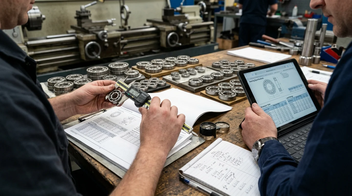
Transitioning from operational parameters to bearing specifications requires navigating a complex matrix of dimensional tolerances, internal geometries, and material science. Selecting the optimal combination ensures the bearing achieves its calculated kinematic lifespan without thermal runaway or excessive vibration.
Load, speed, precision, clearance, and preload
Load ratings dictate the bearing’s physical sizing, while precision classes—defined by ABEC (1 through 9) or ISO (P0 through P2)—govern runout tolerances. For standard industrial gearboxes, ABEC 1 or 3 is typically sufficient, maintaining radial runout within 10 to 20 micrometers. However, high-speed machine tool spindles demand ABEC 7 or 9 to prevent catastrophic harmonic vibration.
Internal clearance is another critical variable; standard clearance (CN) may bind under high thermal expansion, necessitating a C3 or C4 designation. For example, a 50mm bore bearing with C3 clearance provides 13 to 28 micrometers of radial play to accommodate thermal growth. Preloading is often applied to eliminate this internal clearance entirely, increasing system rigidity and shifting the load distribution across multiple rolling elements to prevent ball skidding at high rotational speeds.
Materials, cages, seals, lubrication, and temperature limits
Material selection directly limits the bearing’s thermal and environmental capabilities. Standard SAE 52100 chrome steel offers excellent fatigue life but suffers from dimensional instability above 120°C. For corrosive environments, AISI 440C stainless steel provides superior resistance, though it sacrifices approximately 20% of the dynamic load capacity compared to 52100 steel.
Hybrid bearings utilizing silicon nitride (Si3N4) ceramic balls reduce centrifugal forces by 40%, allowing for 20% to 30% higher operating speeds while mitigating electrical pitting in variable frequency drive (VFD) motors. Lubrication fill rates must also be specified; a standard 25% to 35% grease fill by volume prevents churning and overheating at high speeds, while low-speed, high-load applications may require up to a 50% fill.
| Component Material | Max Operating Temp | Relative Dynamic Load | Corrosion Resistance | Typical Cost Premium |
|---|---|---|---|---|
| 52100 Chrome Steel | 120°C (standard) | 100% (Baseline) | Low | 1.0x |
| 440C Stainless Steel | 150°C | ~80% | High | 2.5x – 4.0x |
| Hybrid (Ceramic Balls) | 200°C+ | ~100% | Very High | 5.0x – 8.0x |
Ball bearing types and their industrial trade-offs
The internal geometry of a ball bearing dictates its functional limits. While all ball bearings utilize point contact to minimize friction, variations in raceway design optimize them for specific combinations of radial forces, axial thrust, and shaft deflection.
When to use deep groove, angular contact, and self-aligning bearings
Deep groove ball bearings (DGBB) are the industry standard for versatility, capable of supporting heavy radial loads and moderate axial loads (typically up to 25% to 50% of the pure radial capacity) in both directions. They are the default choice for electric motors and standard conveyors.
When the application involves dominant unidirectional axial forces—such as in vertical pumps or heavily loaded gearsets—angular contact ball bearings (ACBB) are required. These bearings are manufactured with specific contact angles, most commonly 15°, 25°, or 40°. A steeper 40° angle significantly increases axial load capacity at the expense of maximum radial speed. Self-aligning ball bearings feature a spherical outer raceway, making them indispensable in agricultural or heavy textile machinery where shaft deflection or mounting inaccuracies are prevalent.
Comparing load direction, speed, and misalignment tolerance
Comparing these topologies requires assessing their limiting speeds and misalignment tolerances. Deep groove bearings offer the highest speed ratings due to minimal sliding friction, but they are unforgiving to misalignment, typically tolerating less than 0.1 degrees before internal stresses escalate exponentially and cause edge loading.
Angular contact bearings must be mounted in pairs (back-to-back, face-to-face, or tandem) to handle bidirectional thrust and require rigid, highly accurate shaft alignment. In contrast, self-aligning ball bearings can accommodate dynamic misalignment of 2.0 to 3.0 degrees without increasing friction or generating excessive heat, though their point-contact geometry on the outer ring limits their overall load-carrying capacity compared to DGBBs of the same envelope.
| Bearing Type | Primary Load Support | Max Misalignment Tolerance | Limiting Speed Factor |
|---|---|---|---|
| Deep Groove | Radial + Moderate Axial | < 0.1° | Very High |
| Angular Contact | High Unidirectional Axial | < 0.05° | High |
| Self-Aligning | Radial (Low Axial) | 2.0° – 3.0° | Moderate |
How to evaluate ball bearing suppliers and quality control
Identifying the correct bearing specification is only half the engineering challenge; securing a reliable supply chain is equally vital. The industrial bearing market is highly fragmented, and quality control disparities between manufacturers can severely impact equipment lifecycle and safety.
Certifications, traceability, and inspection methods
Evaluating a supplier begins with their quality management systems. ISO 9001 is a baseline, but manufacturers adhering to IATF 16949 demonstrate more rigorous automotive-grade process controls. Traceability is paramount; procurement should mandate EN 10204 3.1 material certificates to verify steel purity, as non-metallic inclusions are primary instigators of subsurface fatigue spalling.
Furthermore, acoustic emission and vibration testing are critical QA metrics. Industrial electric motors require bearings graded to specific vibration classes, such as V3 or V4, to ensure quiet operation and minimal harmonic resonance. Top-tier manufacturers utilize automated inline inspection to maintain defect rates below 50 parts per million (PPM), a metric that should be explicitly requested and verified during supplier audits.
Lead times, sourcing channels, and counterfeit risk
Logistics and supply chain security introduce significant risk factors that procurement must navigate. Lead times for specialized configurations, such as high-precision angular contact pairs or custom high-temperature grease fills, routinely extend to 16 to 24 weeks. Procurement teams must balance inventory carrying costs against the severe risk of production stockouts.
Additionally, the proliferation of counterfeit bearings poses a severe threat, costing the global industry an estimated $3 billion annually and introducing catastrophic safety risks into heavy machinery. To mitigate this, sourcing must be strictly restricted to factory-authorized distributors. Utilizing anti-counterfeiting tools, such as the World Bearing Association (WBA) authentication app, allows incoming quality control teams to verify matrix codes on packaging directly against the manufacturer’s secure database.
A practical process for selecting cost-effective ball bearings

Bridging the gap between engineering requirements and procurement realities requires a systematic selection workflow. A structured approach ensures that technical specifications are met without inflating the total cost of ownership (TCO) or creating supply chain bottlenecks.
Step-by-step workflow from application data to specification
The selection workflow should strictly follow a data-driven sequence. Step one involves defining the required L10 basic rating life, which typically ranges from 20,000 hours for general industrial machinery to over 100,000 hours for critical continuous-operation power generation equipment. Step two utilizes the application’s duty cycle to calculate the equivalent dynamic bearing load (P).
Step three maps this load requirement against available boundary dimensions (bore, outside diameter, and width) to select a preliminary bearing size. The final step refines the selection by specifying cages, seals, and lubrication based on the thermal and environmental data gathered. This iterative process ensures the bearing operates within its optimal load zone, ideally between 2% and 10% of its dynamic capacity, to prevent skidding and smearing of the raceways under light loads.
How engineering and procurement should finalize the choice
Finalizing the choice requires a synergistic effort between engineering and procurement to evaluate the TCO rather than just the piece price. While a Tier 2 bearing might offer a $5 upfront saving per unit over a Tier 1 alternative, a resultant 15% reduction in MTBF could trigger thousands of dollars in premature maintenance labor and warranty claims per machine.
Procurement must also negotiate minimum order quantities (MOQs) effectively. By working with engineering to standardize shaft sizes across multiple equipment lines, a company can aggregate demand, easily surpassing the 1,000-unit MOQ thresholds often required to unlock volume pricing from premium manufacturers. This standardization strategy reduces inventory complexity, lowers unit costs, and maintains uncompromised mechanical reliability across the entire product portfolio.
Key Takeaways
- The most important conclusions and rationale for ball bearings
- Specs, compliance, and risk checks worth validating before you commit
- Practical next steps and caveats readers can apply immediately
Frequently Asked Questions
What data should I define before choosing a ball bearing?
Confirm shaft/housing size, radial and axial loads, RPM, temperature range, and contamination level. These inputs let you match load rating, clearance, seals, and lubrication correctly.
Which ball bearing type is best for mainly radial loads?
Deep groove ball bearings are usually the first choice. They handle high speed, moderate axial load, and are widely used in motors, conveyors, and general industrial equipment.
When should I choose C3 clearance instead of standard CN?
Use C3 when higher speed, heat, or tight fits will increase internal stress. It helps prevent binding after thermal expansion in motors and continuous-duty machinery.
Should I select sealed or open ball bearings for dusty or wet equipment?
Choose sealed bearings for dust, moisture, or limited relubrication access. Open bearings fit cleaner systems with controlled lubrication, such as oil bath or centralized grease setups.
How can DEMY Bearings help with bearing selection?
You can use DEMY’s e-catalog to compare ball bearing types and specifications, then contact the team for OEM or industrial application matching based on load, speed, and environment.